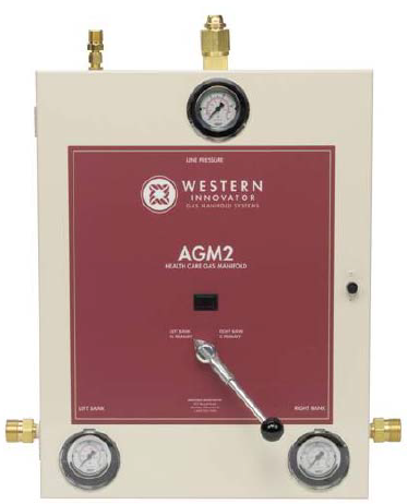
Western Analog Manifold
Automatic Changeover Medical Gas Manifold
The automatic changeover manifold is designed to provide a reliable uninterrupted supply of gas to a hospital or clinic’s
medical gas pipeline system. It is designed to meet NFPA 99 type 1 facility requirements.
The automatic changeover manifold is designed to provide a reliable uninterrupted supply of gas to a hospital or clinic’s
medical gas pipeline system. It is designed to meet NFPA 99 type 1 facility requirements.
- 24” flexible stainless steel braided pigtails, except oxygen which include rigid copper pigtails. Vertical crossover and staggered configurations include 36” pigtails for half of the cylinders. All pigtails include a check valve.
- CGA connections with integral check valves at each header station.
- Special header configurations available upon request. (U-shaped, L-shaped, etc.) (Dimensional sketch of installation required).
- Built for expansion by adding header extensions.
Manifold Design
The manifold control includes the following components and features: green “system normal” and red “replace depleted
cylinders” indicator lights, analog gauges for both cylinder pressure and line pressure, line pressure gauge, internal dual
line assembly and line relief valve. The control unit shall automatically switch to the secondary bank when the service
bank is depleted. When the depleted cylinders are replaced with full cylinders, the operator should then turn the control
knob to the opposite cylinder bank. This will make the partially used “Secondary bank” the “Service” supply and the
newly installed cylinders will become the “Secondary “ supply. The system incorporates a fail-safe configuration so that
the red light can only be extinguished when sufficient pressure is supplied from both banks.
Supply banks consists of a header with 24” stainless steel flexible pigtails with check valves, except oxygen which
include rigid copper pigtails with check valves, individual spud check valve bushings, master shut-off valves, and union
connections for attachment to the control unit. Under normal operating conditions, the gas shall leave the high pressure
cylinders through the pigtails into the header bars. The pigtails shall include check valves to allow the replacement of
depleted cylinders without gas pressure back-flow into the remaining depleted cylinders on that bank.
A separate power supply is furnished with the manifold to convert 120 VAC to 24 VAC output power and includes dry
contacts for connecting the “Reserve in Use” alarm to the facility’s master alarm panel/s. The power supply is housed in
a NEMA 3R, enclosure with electrical requirements of 1.5 amp at 120 VAC, 1Ph, 60 Hz. The power supply is CSA
approved.

 Submit Quote
 View RFQ

 = Required