
 Submit Quote
 View RFQ
Area Alarm Part Configurator
Medical gas area alarms are used to monitor Oxygen, Medical Air, Medical Vacuum, Nitrous Oxide (N2O), Carbon Dioxide (CO2), Nitrogen, Waste Anesthetic Gas Disposal (WAGD / EVAC), and instrument (lab) air in specific zones of medical facilities. Medical gas area alarms are required to monitor all critical care and procedure areas in medical facilities and hospitals.
- LCD alarm panel incorporates the latest microprocessor based technology
- Smallest 8 gas alarm in the industry
- Auto detecting gas sensors (no need to set dip switches)
- Sensors designed to create interference barrier for increased RFI/EMI protection
- LCD brightness and volume is field adjustable
- LCD display readable in poor lighting conditions
- Self diagnostic and error message display for ease of maintenance
- Customizable screen text for gas locations
- High / Low alarm set points are field adjustable for each individual gas service
- Gas specific sensor with DISS nut and nipple
 = Required
GENERAL SPECIFICATIONS
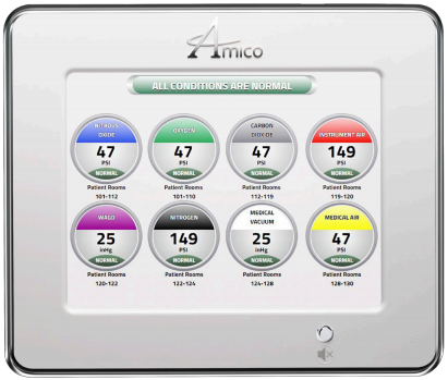
- The Digital LCD Area Alarm system shall be an Amico Alert-3 series. The LCD alarm shall be microprocessor based with a 10" (25.4 cm) screen and capable of monitoring up to 8 sensors.
- Sensors shall be mounted locally (in the rough-in box) by installing the copper pipe provided or mounted remotely. Sensors will be automated for gas specific detection. Each sensor unit is gas specific, with an error message display for an incorrect connection.
- Each specific service shall be provided with a digital read-out comprising of 0-249 psi (0-1,717 kPa) for pressure and 0-30 inHg (-100-0 kPa) for vacuum. The digital read-out shall provide a constant indication of each service being measured. An indicator shall be provided for each service indicating a green “NORMAL” and a red “HIGH” or “LOW” alarm condition. If an alarm occurs, the green indicator will change to red and a continuous audible alarm will sound. Pushing the (mute button/push to test button) will cancel the audible alarm, but the unit will remain in the alarm condition until the problem is rectified.
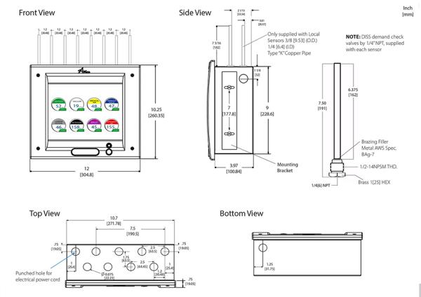
- The default set-points shall be +/- 20% variation from normal condition. In the calibration mode High/Low set-points shall be adjustable by on board push buttons. To view the set points and audible alarm sound level, press and hold the mute button for twenty (20) seconds. The box shall be fabricated from 18 gauge (1.3 mm) steel with a 3/8" (9.53 mm) O.D. type “K” copper pipe for connection to the service line.
- The box mounting brackets shall be adjustable to accommodate for different wall thickness. LCD Sensor operating pressure range: Mid-Pressure: (0 psi to 99 psi) - OXY, AIR, N2O, CO2 High Pressure: (0 psi to 249 psi) - IAR, NIT Vacuum: (0 to 30 inHg) - VAC, WAGD, AGSS Input power to the Amico Alert-3 alarm is: 115-220 VAC, 50-60 HZ. The Amico Alert-3 LCD Alarm conforms to UL Standard 1069 and is certified to CSA Standard C22.2 No. 205. Amico products comply with NFPA 99 and CSA Z7396.1.
- The Amico Alert-3 LCD Alarm complies with the following electromagnetic compatibility standards: FCC Part 15 Class A and ICES-003 Class A.